Development of an EMG-Driven Wearable Knee Exoskeleton for Assistive Rehabilitation
Timeline
Oct 2024 - Jun 2025
TYPE
Academic
Engineering Design
Team Project
RoLE
Main Mechanical Designer
DELIVERABLEs
3D CAD model
Mechanical Analysis
Physical Prototype
Torque Testing
TOOLS

SolidWorks

Ansys

MATLAB

Arduino

ChatGPT
This is an engineering design project that aims to create a device with Variable Stiffness Actuators (VSAs) to help patients in knee rehabilitation exercises. This is the capstone project for my Bachelor Degree in Mechanical Engineering at VinUniversity, and a collaboration of four students from different engineering background.
problem
Knee rehabilitation is an important part of the recovery process for patients after an accident or surgery. This is a slow and inefficient process and requires a lot of support from clinicians. This heavy reliance on clinical expertise not only limits scalability but also places significant strain on healthcare resources.
goal
Design a device to replicate the support from clinicians during knee rehabilitation exercises by using Variable Stiffness Actuators.
Members & Responsibilities
Supervisor Professor
Provide assistance and guidance for the team. Help members navigate through obstacles to receive the desired result.
Duy-Quang (it's Me)
Mechanical Design & Analysis. Design the core mechanisms and elements of the device.
Collab in System Control.
Collab in System Control.
Member 2
Manufacturing. In charge of material selections, manufacturing methods and executions.
Collab in System Control.
Collab in System Control.
Member 3
Electrical Design. Responsible for the electrical components, focus on EMG signal processing & data gathering.
Collab in System Control.
Collab in System Control.
Member 4
AI application. Focus on training AI model to predict angle output from inputs of EMG signals.
Collab in System Control.
Collab in System Control.
THE Design PROCESS
I. Initial Research:
Approaching this project, the team first examined current VSAs design via scientific entries to identifying the key features of VSAs:
Key characteristics of VSAs
Adjustable stiffness
The rotational stiffness of the device usually dynamically adjusted.
Elastic Components
Usually a spring acting as the main elastic component. Ensures smooth, flexible movements.
motors
Dynamic stiffness control by two motors or 1one motor and one return spring.
Control & Sensing
Real-time sensing for immediate responsiveness.
From the literature review, one VSA design stand out for it's simplicity and high efficiency. We decided to adopt a similar design principle with Bacek et al. (2018) for our device.
MACCEPA + PEA Design Principle (Bacek et al. 2018)

II. IdeatION:
Inspired from the design of Bacek et al. (2018), our team decided the main components of our device. As the main Mechanical Designer, my responsibilities revolve around investigate and decide on the mechanisms, choose suitable springs and motors. I also participate in the controlling process, providing mechanical insights and calculations.
Elements of our device
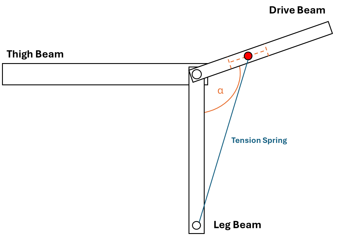
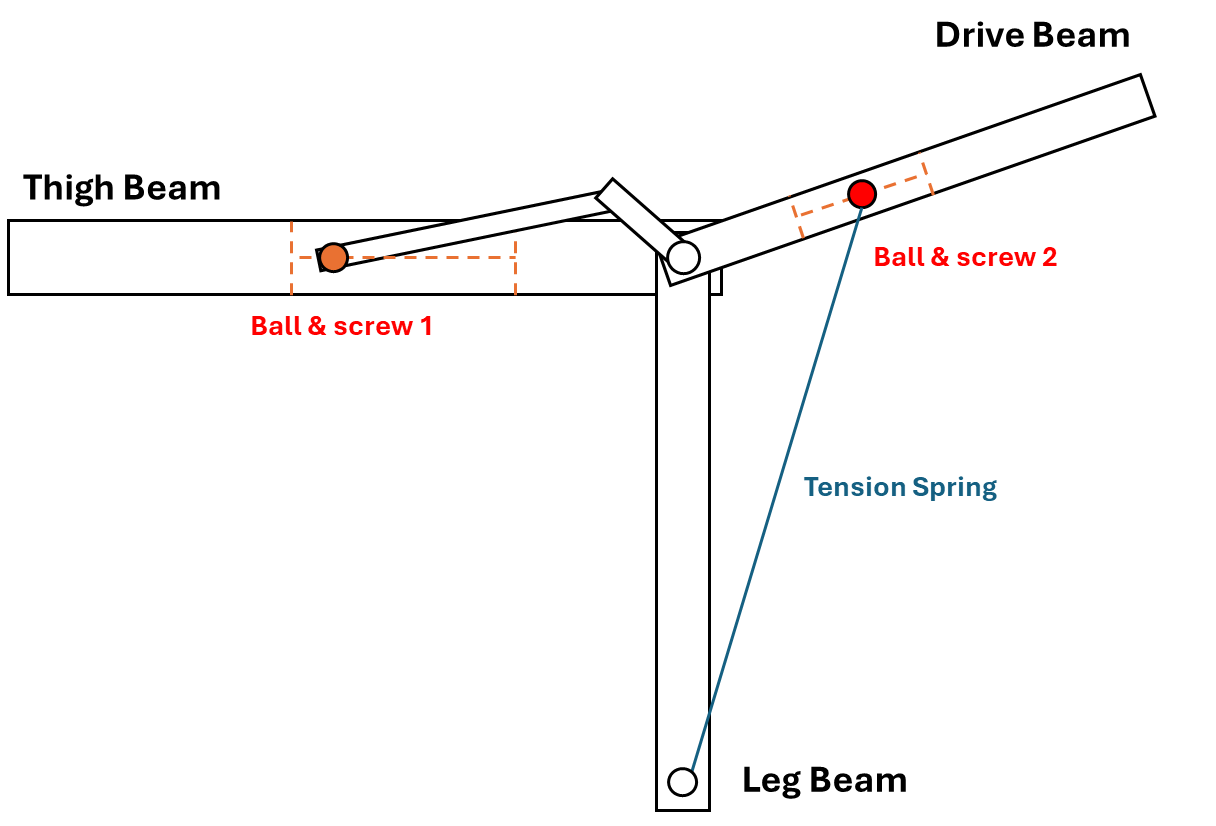
Beams
Consists of 3 main beams: thigh, leg, and drive beam.
Elastic Components
Tension spring attached between the drive beam and the leg beam.
Motors
Two high-torque stepper motors control the stiffness
Principle
One motor control drive beam angle, another adjusts spring position.
Sensing
EMG sensors get the electrical signals when the user move their legs.
Machine learning
AI model receive EMG signal as inputs and give out according angle of the user's leg.
Early Stage - Low Fidelity Design - SolidWorks
III. Mechanical Design:
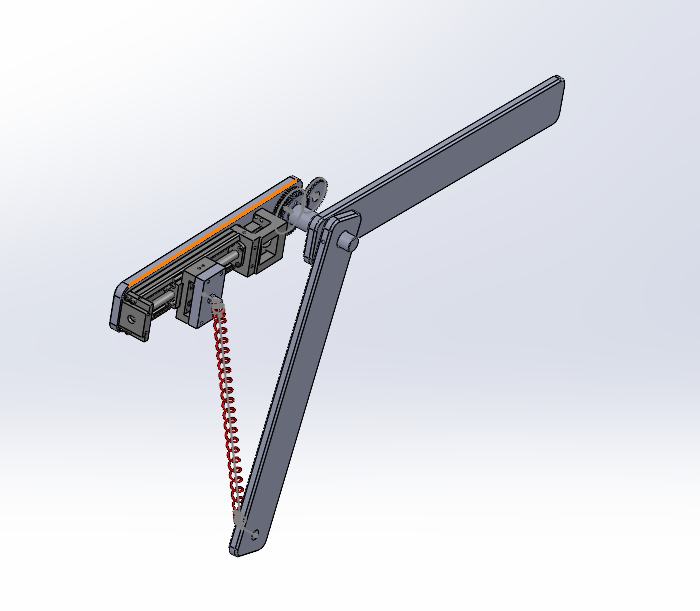
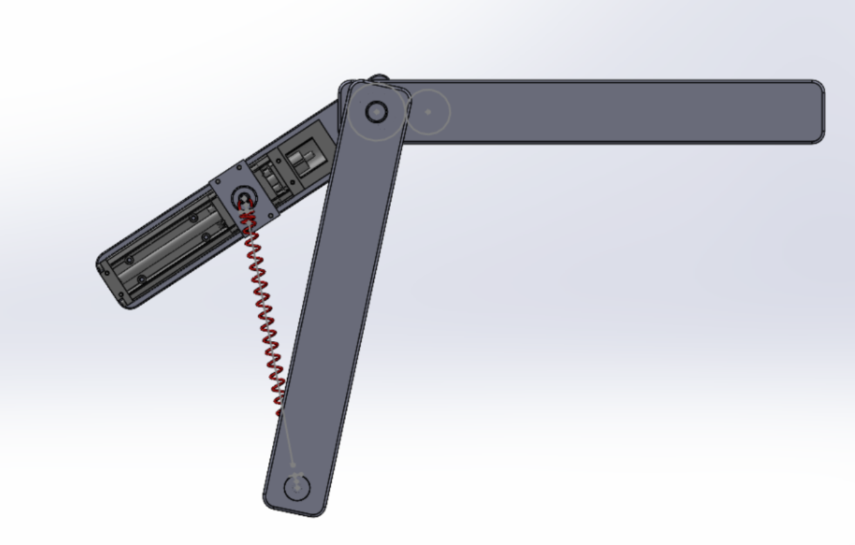
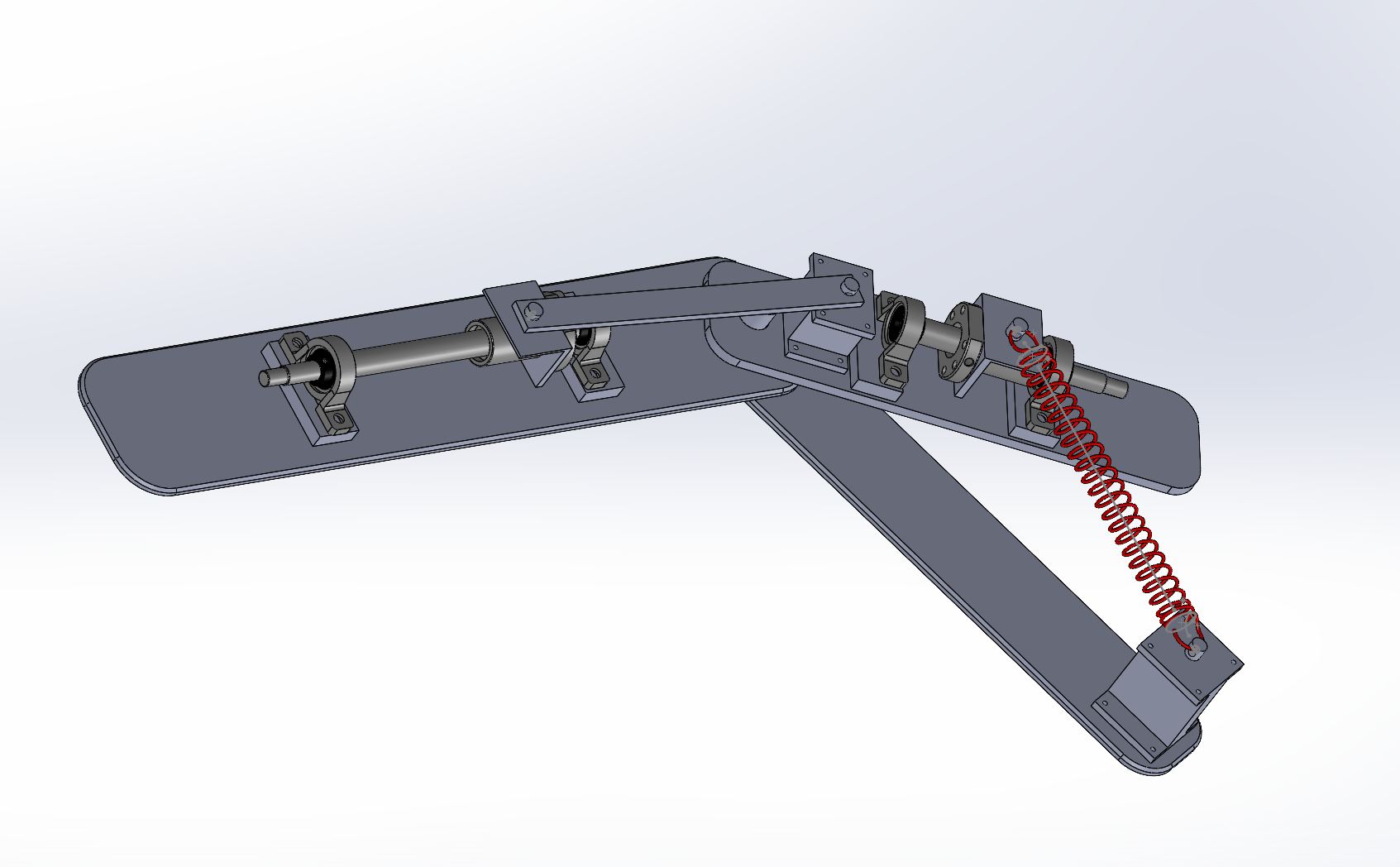
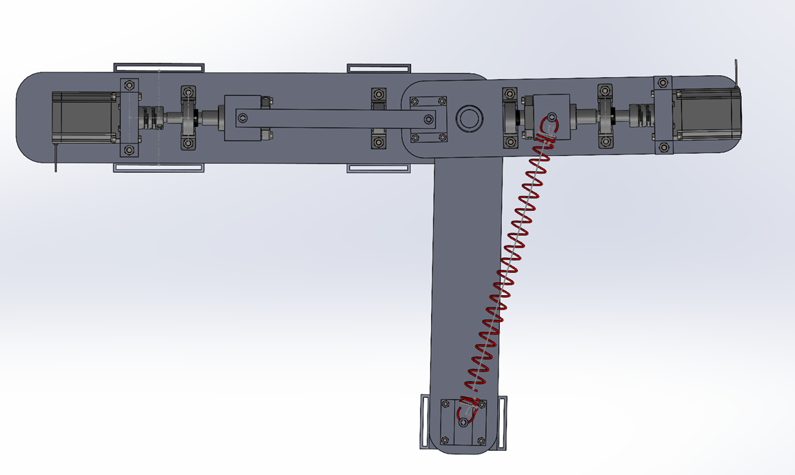
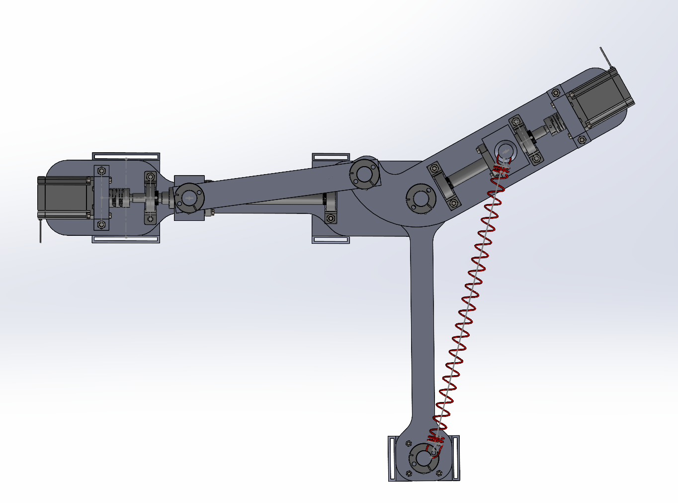
After experimenting with different mechanical approach in SolidWorks, along with the guidance of our professor, our team decided that we would use two set of ball-screw that convert the rotational motions of the motors to linear motions. The linear motions will then be used to control the angle of the drive beam through the principle of the crank-slider mechanism.
Mechanism Design
IV. Analysis & Simulation:
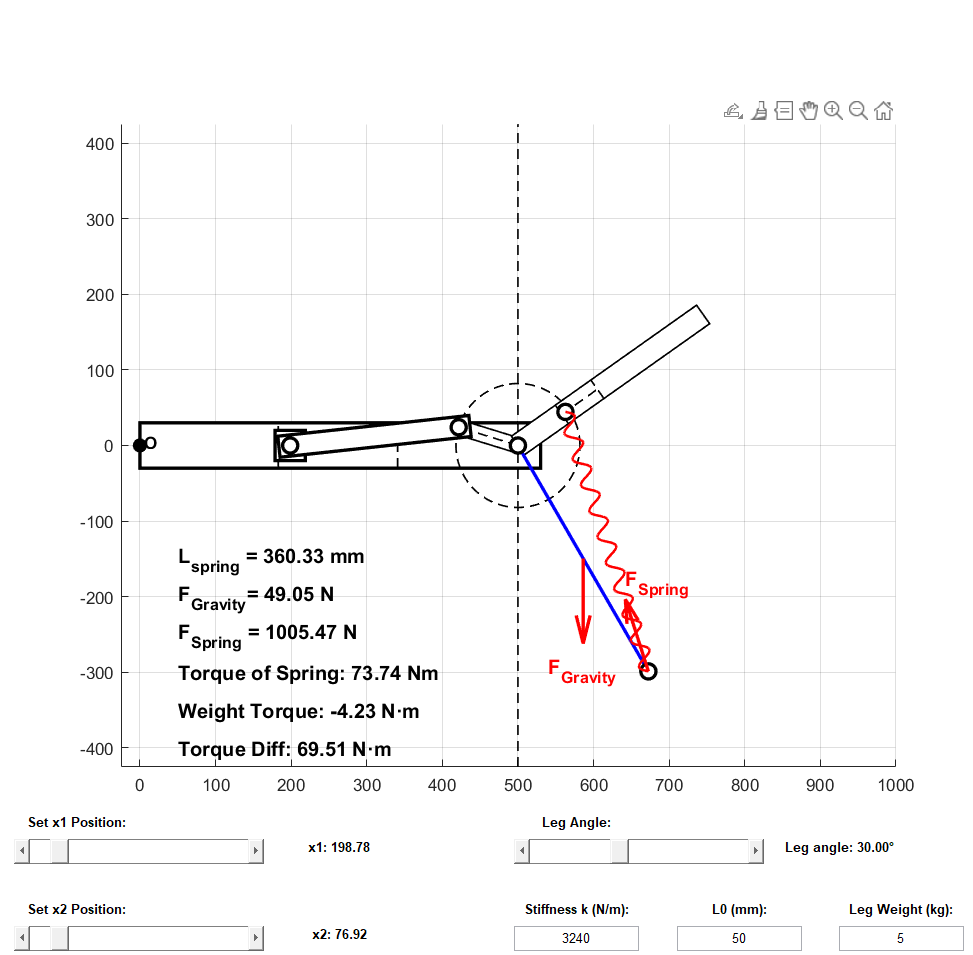
From the design, I create a dynamic model to help calculate the output torque of the device based on the positions of the motors and the leg's angle. I also use MATLAB & ANSYS to create a simulation of the device to better understand the torque relationship and the beam strength.
Torque-Control Equation


MATLAB Simulation
ANSYS Simulation


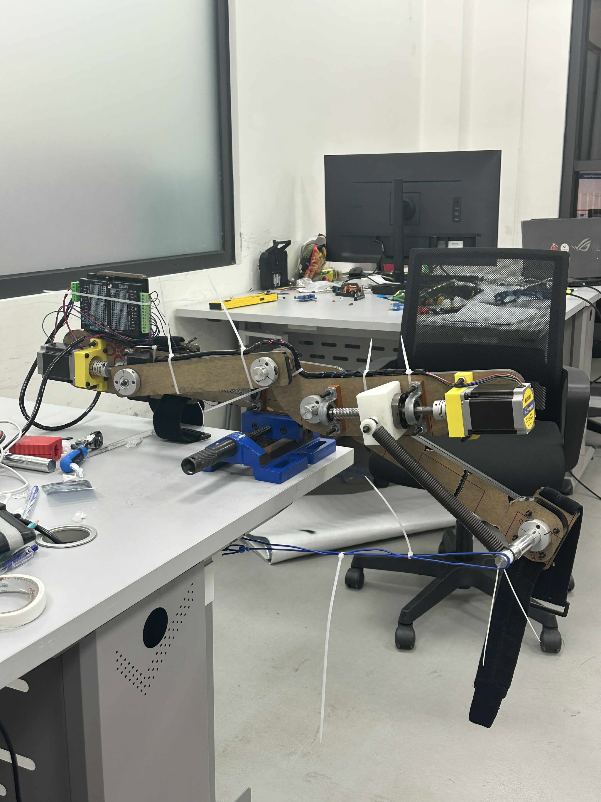
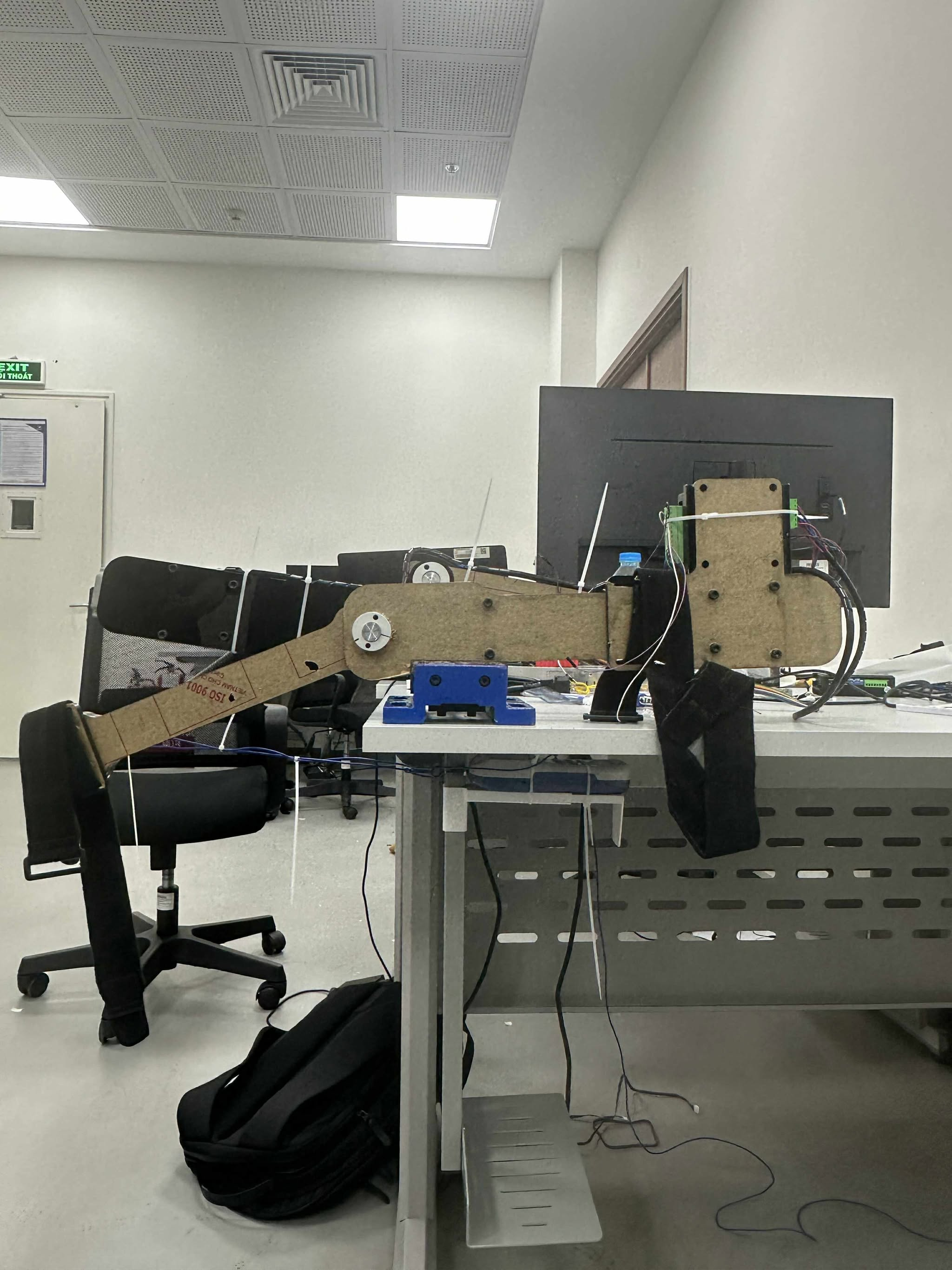
V. Prototyping:
With the High Fidelity Design, our team started working on the the physical prototype. The beams were made by laser cutting plastics. The shafts were be made by lathing using CNC machines. Other elements will be bought or 3D printed.
Prototype 1.0
.jpg)
.jpg)
Problems & Solutions
Velcro Strap
3D printed strap too brittle, the location of the strap is not user friendly.
Solution
Convert the strap to Acrylic Plates. Relocate the location of the strapping point.


Tolerance
Tolerance make the device is wobbly, with some parts cannot be fitted together.
Solution
Cut a plate with holes in different size to test the tolerance. Use tapes to test the tolerance of the metal shafts. 3D printed with different size to test.


Beams
The beams made with 5mm MICA plates are bent due to the spring force and the device's weight.
Solution
Make the beam with 10mm MICA plates.


Failed Parts

Prototype 2.0 (Final)
.jpg)
.jpg)
VI. Mechanical Validation :
After the final prototype was made, the team conducted a torque test to validate the performance of the device. The test is set up as follow.
Torque Test


Torque Results (Nm)

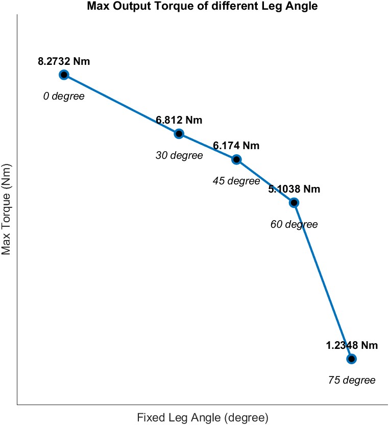
The test results shows that the device can produce the maximum torque of 8.3Nm when the user's leg is at 0 degrees (perfectly vertical), with the drive beam and the spring pin both at the highest position possible. The test also show drastic drops of the output torque when the drive beam is near the leg beam. In these configuration, the output torque is near 0Nm.
VII. Final Design:
System Architecture


Final Mechanical Design

Takeaways
This project was a valuable experience that allowed me to collaborate with students from other engineering background and provided me with hands-on engineering design experience. The engineering design process, from examining the problem, research, ideate, design, prototype, and testing are conducted methodologically, and help me have a better sense in engineering design.
Key Learnings
Engineering system design
Full engineering design process. Hands-on experiences with every phase of the design process.
Mechanical Design
Improve my knowledge with mechanical design, from creating CAD models, running simulation, to rapid prototyping and testing.
Interdisciplinary collaboration
Communicate, support, collaborate with people from other background to finished the project.
References
[1] T. Bacek, E. Rombokas, and H. Asada. A modular maccepa with parallel elasticity for kneeexoskeletons. Mechanism and Machine Theory, 130:71–85, 2018.