PNeumatic CNC Coolant Filter
Timeline
May - Jun 2023
TYPE
Academic
Engineering Design
Solo Project
RoLE
Solo Designer
DELIVERABLEs
3D CAD model
TOOLS

A. Inventor
This is a design for a mobile filter that can be used to clean CNC coolants from CNC machines. This device can help increase factory efficiency, save time & effort for the workers. This was a personal project during my internship at SMC, aiming to solve the problem in the manufacturing factory.
problem
CNC machines use a special coolant oil to prevent overheating while doing the machining. This liquid usually contains small fragments of metal. After sometime, the liquid need to be filtered in order to keep the machine working. This process is time consuming and put the workers at health risks.
goal
Design a filter machine that use diaphragm pumps to help filter the coolant oil automatically, saving time and effort for the factory's worker.
THE Design PROCESS
I. Initial Research:
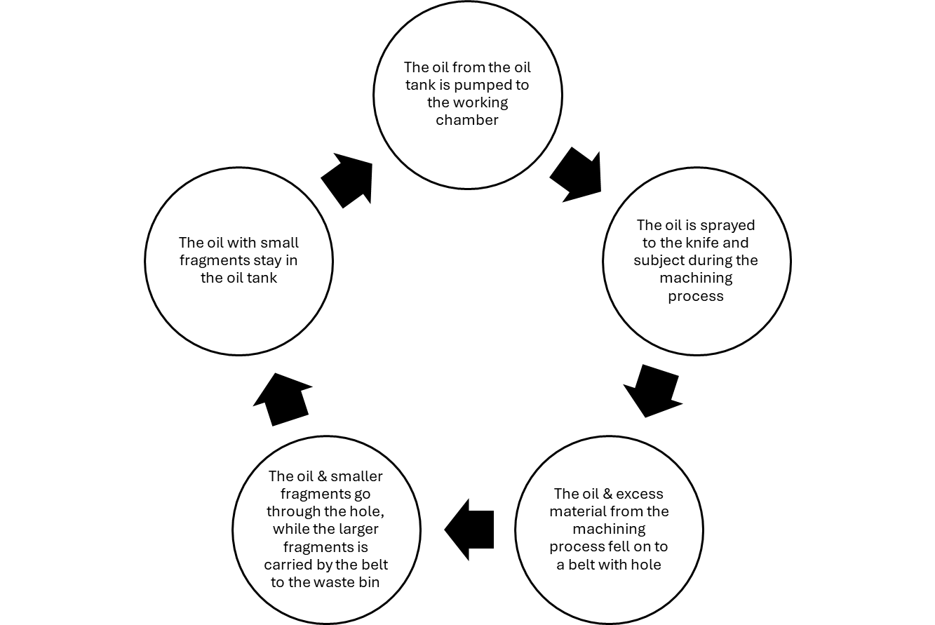
Approaching this project, I started by examining the CNC machines to gather necessary information related to the design. I examined the coolant cycle, how the CNC machine filtered the coolant, and conducted competitive audit on the current solution available on the market.
Examining the filter system at the machine
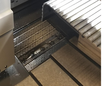
Belt with hole
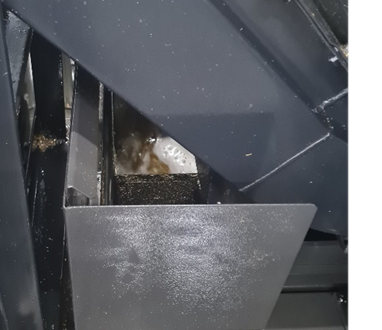
Coolant carry tiny Fragments back to the tank
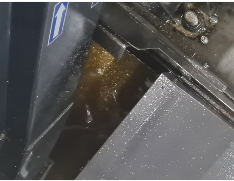
Coolant Tank filled with small metal fragments
Larger fragments in the Waste Bin
Each month, the workers have to stop the machine, open up the oil tank, take out and filter the machining oil, clean up the tank, then pour the oil back to the machine. This is a complicated and time-consuming process. Putting this in a larger scale leads to a lot of revenue loss for the factory. Manually take the oil out and filter it could also increase the risk of having an environmental emergency case inside the factory and could be harmful for the workers.
Characteristics of CNC Machines
Volume
The largest CNC machine can contain 260L of machining oil inside its tank.
Placement
Oil tanks are placed on the ground, underneath the main working chamber. The height is about 30cm tall.
Time
The desired time to clean a machine would be around 10-20 minutes.
Mobility
The device have to be mobile so that it can be deploy easily by workers everywhere inside the factory.
Power Supply
The factory have pneumatic air outlet attached on the wall, and electric outlets attached really high on the ceiling.
Maintenance
Has to be able to replace or attached additional filters, so that it can filter both large particles and tiny particles with just a filter change.
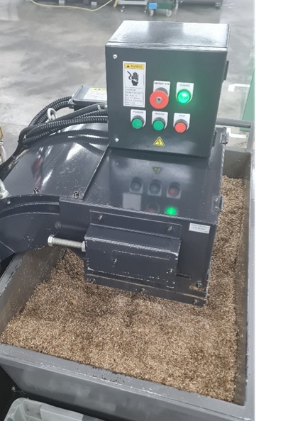
Competitve Audit: Delfin Industrial Vacuum
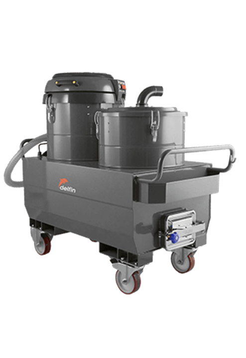
A solution from Delfin
Coolant cycle
II. IdeatION:
Pump of Choice
This task consists of industry chemicals, large and small solids particles mixed inside the liquid. Hence, the machine need to use a special kind of pump called Diaphragm Pump to prevent clogging.
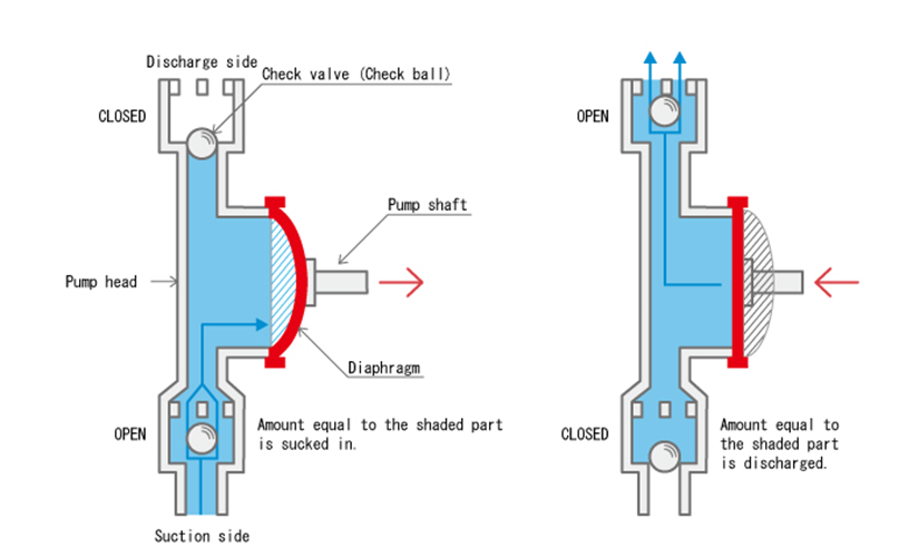
Diaphragm Pump Working Principle
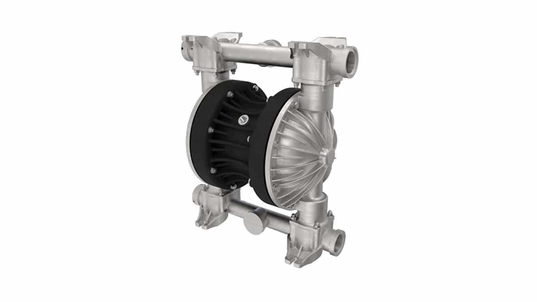
Diaphragm Pump
Design Ideas
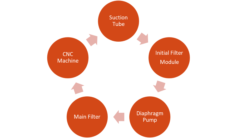
Fish-tank Design
The first idea would be creating a device similar to the fish tank filter.
CNC Machine cannot be fully cleaned
Oil is not fully taken out of the CNC machine tank. Cannot clean up the oil tank, scrap off the sticky dirt. Some fragments might stay in the oil tank.
Increase Risk and Price
To fully filter the oil, the pump has to be able to let large particles going through. If the particle is larger than the pump limit, it can create a clogging risk for the pump.
Faster & UninteRrupted
Faster to deploy & the filtering process is faster, and can be use when the CNC machine is working.
The second idea is a device that could take the oil out completely and filter them externally.
CNC Machine can be fully cleaned
Leave room for further cleanup of the oil tank and scrapes out the sticky waste.
Bigger in size
Needs a minimum of two internal tanks to store the pre-filtered oil and filtered oil.
Slower & Interrupt the CNC MAchines
The machine will have to be stop until the filtering process is cleaned.
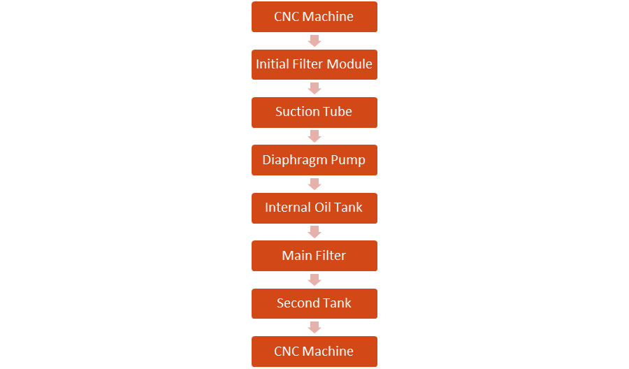
External-stored Design
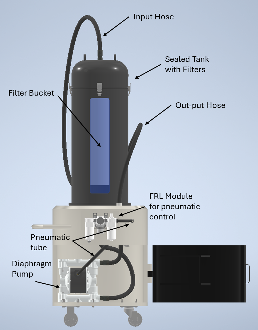
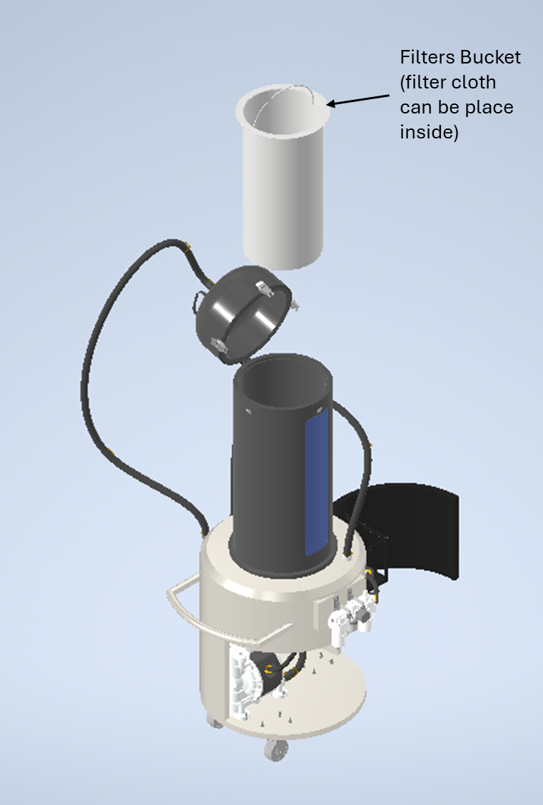
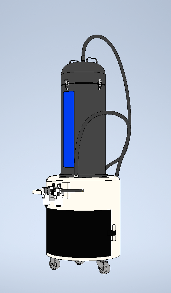
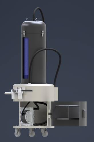
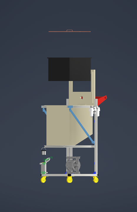
III. Final Designs:
Because of the time limit, I decided to choose the first design to create 3D models using Autodesk Inventor. I attempted to create two different models for this design, one made from shaped aluminum and other easy to find material, the other is the better looking version, yet the manufacturing process would be more complex.
Takeaways
This project was a valuable experience for me. I gained hands-on experience with product design. I followed each step carefully, from examining the problem, researching current solution on the market, defining requirements, creating 3D models for my idea.
Through this project, I became familiar with the factory's machines, the factory's procedures, and 3D tools like Autodesk Inventor Professional. I also got the chance to apply the knowledge learned in courses like Fluid Mechanics, Dynamics, and Pneumatic to this design project.
Through this project, I became familiar with the factory's machines, the factory's procedures, and 3D tools like Autodesk Inventor Professional. I also got the chance to apply the knowledge learned in courses like Fluid Mechanics, Dynamics, and Pneumatic to this design project.
Key Learnings
Engineering Design Process
Examining the problem, defining the design requirements, creating 3D models.
Autodesk Inventor
Improve proficiency in using Autodesk Inventor to design mechanical models.
Apply Knowledge
Apply knowledge in mechanical engineering & pneumatic system in the project.